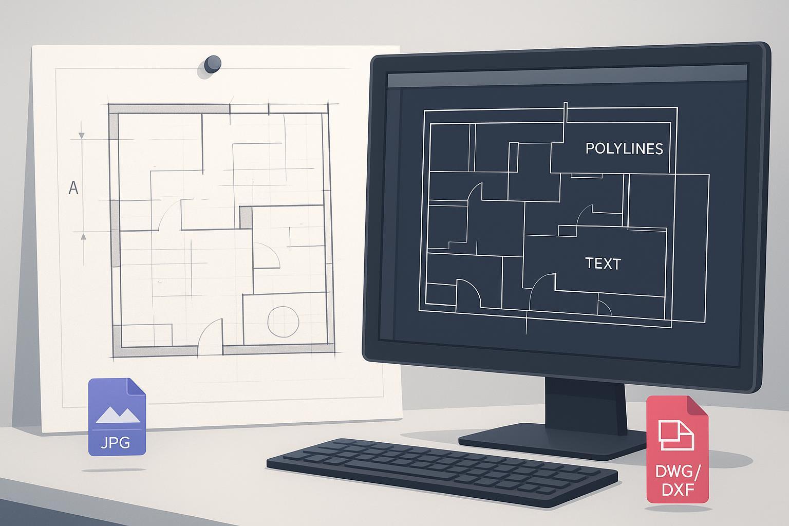
Converting a paper plan or legacy MEP drawing into a clean, fully editable DWG/DXF shouldn't feel like rebuilding the project from scratch. The core challenge isn't just "getting a DXF." It's achieving editability: joined polylines instead of fragments, true arcs and circles, reusable symbol blocks, and real text you can search and restyle. This hands-on guide gives you a reproducible, end-to-end workflow—from scanning through QA—so you can go from raster image to CAD with minimum rework.
Step 1 — Scan for editability, not just readability
Your final CAD quality is capped by your input. For most architectural sheets and detailed MEP plans, target 300–600 DPI. At 300 DPI you'll capture linework and small text reliably; move toward 400–600 DPI for faded, fine-lined, or annotated originals. Multiple digitization guides emphasize this baseline for technical drawings (e.g. University of Illinois 300 PPI minimum for engineering drawings; FADGI technical guidelines).
- Prefer lossless formats: TIFF for archival/technical plans; PNG when TIFF isn't viable. Avoid JPEG for master scans—lossy compression causes artifacts during vectorization.
- Pre-scan checklist: Flatten sheets; scan at 300–600 DPI grayscale/B&W; save TIFF or PNG; confirm orientation and include a known dimension or scale bar.
Step 2 — Preprocess the image to reduce fragmentation
Preprocessing presents your converter with crisp, high-contrast lines and minimized noise. Deskew the page; denoise with light despeckle/median filter; correct perspective if from a phone photo; binarize (global or adaptive threshold, e.g. Otsu/Sauvola); use morphological ops to reconnect breaks or thin bled lines. Test on a small region first.
Step 3 — Vectorize with editability-first settings
Balance line/arc detection thresholds, corner sensitivity, smoothing and curve-fitting tolerance, and gap-closing tolerance. Set minimum entity length below the shortest real segment. Consider disabling automated hatch conversion and re-creating hatches in CAD. Enable OCR so notes and dimensions become MText/Text. After conversion, identify repeated symbols, define blocks, and replace copies.
Step 4 — Calibrate scale and units in CAD
Set drawing units and insertion behavior (-DWGUNITS/INSUNITS). Calibrate scale using a known dimension (SCALE with Reference in AutoCAD; ALIGN for skewed inputs). Verify with DIST on multiple known dimensions.
Step 5 — Cleanup and QA
Run AUDIT; PURGE unused layers/linetypes/blocks; use OVERKILL for duplicates. With PEDIT, join fragmented segments into polylines; rebuild symbols as blocks; clean up layers (LAYMRG). QA: closed polylines where intended; real arcs for door swings/curves; selectable text; block references for repeated symbols; correct scale/units.
Step 6 — Throughput and reproducibility
Define presets for common drawing types and reuse them; log DPI, preprocessing, vectorization preset, OCR bounds, scale method per batch; use batch convert and named profiles where supported.
Practical example — JPG/PNG to CAD online
Use an online converter such as Image to CAD: upload JPG or PNG, choose a technical-drawing preset, enable OCR, export to DWG or DXF. Keep input at 300–600 DPI and spot-check before converting a full set.
Troubleshooting — symptoms and fixes
| Symptom | Likely cause | Practical fix |
|---|---|---|
| Fragmented polylines | Low DPI; weak gap closing; noise | Rescan 300–600 DPI; increase gap-closing; denoise; PEDIT Join with small fuzz |
| Stair-stepped curves | Low resolution; harsh threshold; insufficient smoothing | Higher DPI; adaptive threshold; raise smoothing/arc fitting |
| Doubled edges / ghost lines | Shadows; scanner streaks; JPEG artifacts | Rescan flat; avoid JPEG; deskew/dewarp; thinning |
| Misrecognized text | Low contrast; tight OCR bounds | Improve contrast; widen OCR size/rotation; correct post-export |
| Scale drift | Unknown DPI; unit mismatch; poor calibration | -DWGUNITS; SCALE Reference or ALIGN; verify multiple dimensions |
When to partially redraw
If scans are severely smudged, overprinted, or low-resolution, convert what you can and selectively redraw illegible details. Hatching and stippling are often faster to reapply in CAD than to salvage from noisy rasters.
Closing
Scan cleanly, preprocess thoughtfully, vectorize with editability-first settings, lock units and scale, then run cleanup and QA. Use an online tool like Image to CAD to sanity-check DPI and OCR before finalizing in your CAD.