Can one sofa photo become a usable CAD drawing?
We tested an ordinary studio product photo with no scale and no verified dimensions. The result produced front, side and top CAD views—but the useful part is knowing what can be kept and what still needs to be checked.
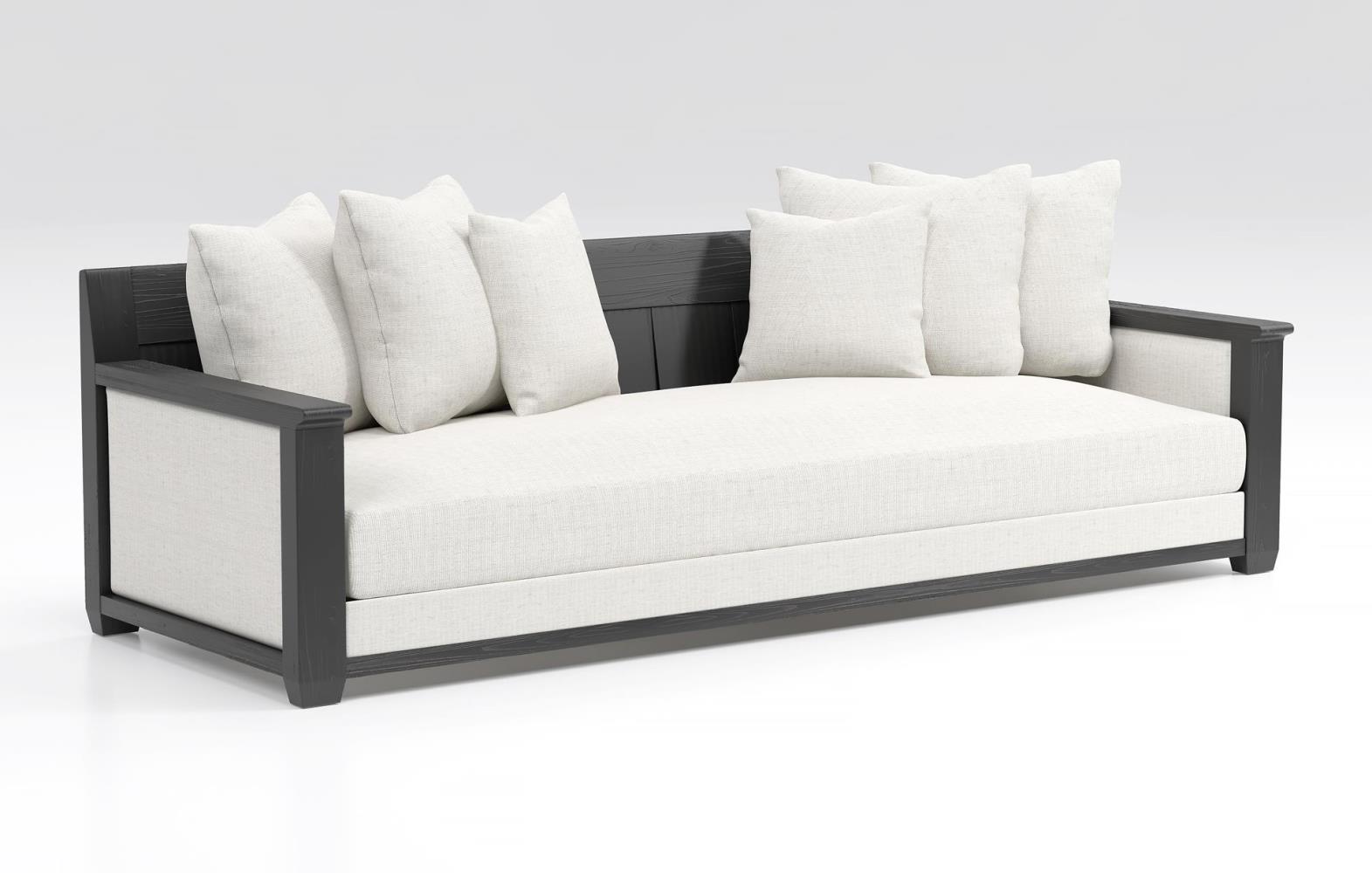
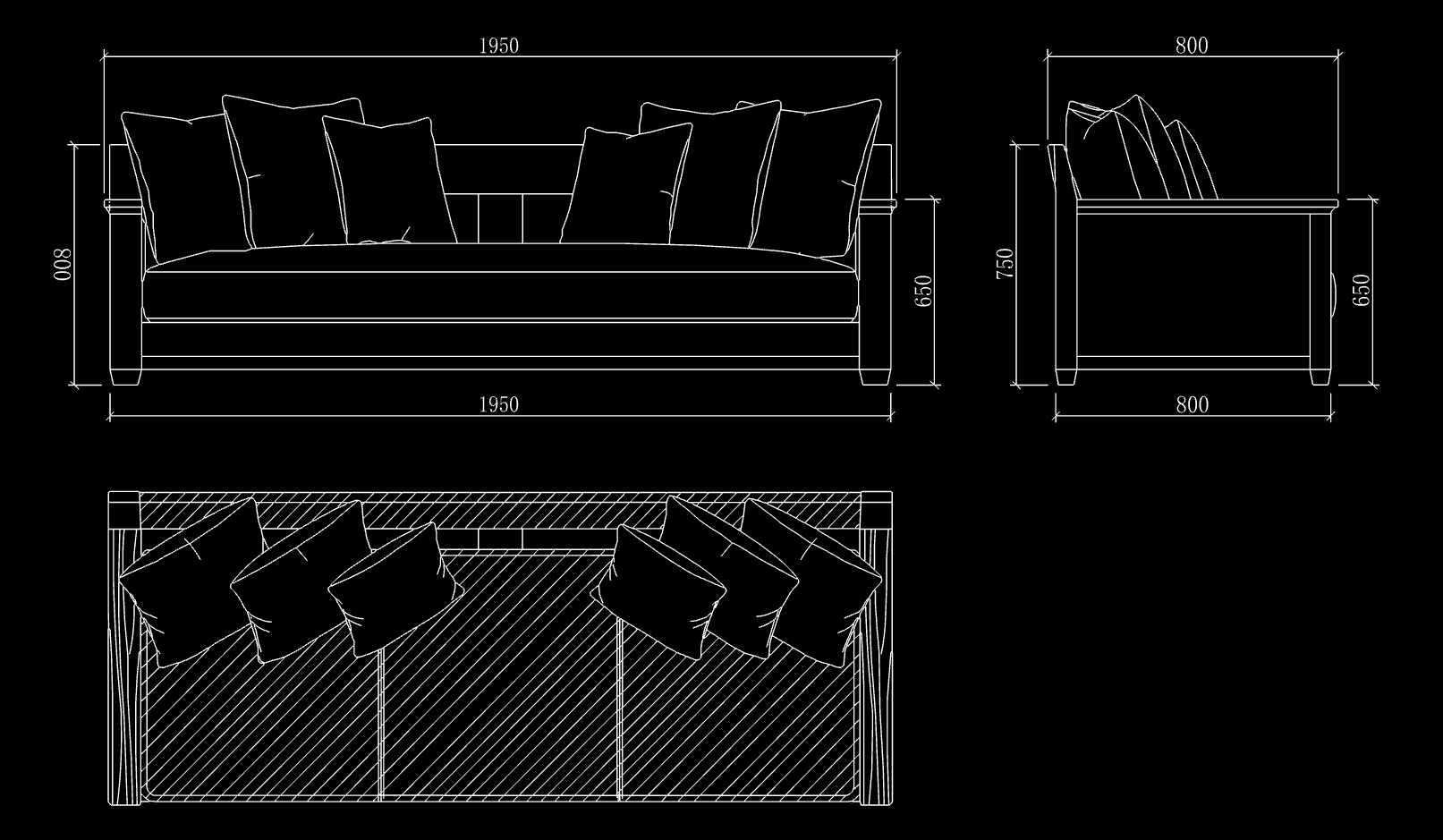
The input was a single oblique product photo. No ruler, scale or verified real-world measurement was supplied.
Dimension notice: labels such as 1950, 800, 750 and 650 were generated or estimated by the system. They were not measured from the physical sofa and must not be used directly for manufacturing, fabrication or construction.
What the conversion produced
The output reorganized the visible sofa shape into a drafting-style result with front, side and top views. The major frame, armrest, cushion and backrest lines are represented in a form that is easier to inspect than the original photograph.
Watch the complete conversion process
Where this result can save time
The practical value is not “a photo becomes a production drawing automatically.” The value is that a CAD user can begin with visible geometry instead of starting from a blank canvas.
- Early layout and space-planning discussions.
- Product and style confirmation before detailed drafting.
- Creating a starting outline for manual correction.
- Organizing batches of product references into a more consistent CAD workflow.
What a single photo cannot prove
A perspective photo contains relative visual relationships, not verified millimeter measurements. It also does not reveal hidden back, top or internal construction details. Any geometry for those areas necessarily involves inference.
- True dimensions: calibrate the drawing with at least one known measurement.
- Hidden geometry: compare additional views or inspect the physical product.
- Engineering details: add material thickness, joints, hardware, tolerances and manufacturing information manually.
- Line quality: check for duplicate segments, small gaps, open contours and unwanted lines caused by texture or shadows.
A safer photo-to-CAD workflow
- Use the clearest source image available, with the object separated from the background.
- Generate the initial CAD result and inspect the overall shape before trusting any label.
- Open the actual CAD file and check outlines, intersections, gaps and duplicate geometry.
- Calibrate the drawing using a known real-world measurement.
- Complete all missing engineering information and obtain professional review before production.
The tool can reduce repetitive tracing. Measurement responsibility and engineering judgment remain with the person preparing the final drawing.
Try an image from your own workflow
Upload a photo, floor plan, sketch or technical drawing, then inspect the generated DWG/DXF result.