Can a furnished floor plan image become editable CAD linework?
This test starts with a finished floor plan containing walls, doors, windows, stairs, sanitary fixtures and furniture. The conversion keeps the main layout as CAD linework, giving a drafter a practical starting point for checking and editing.
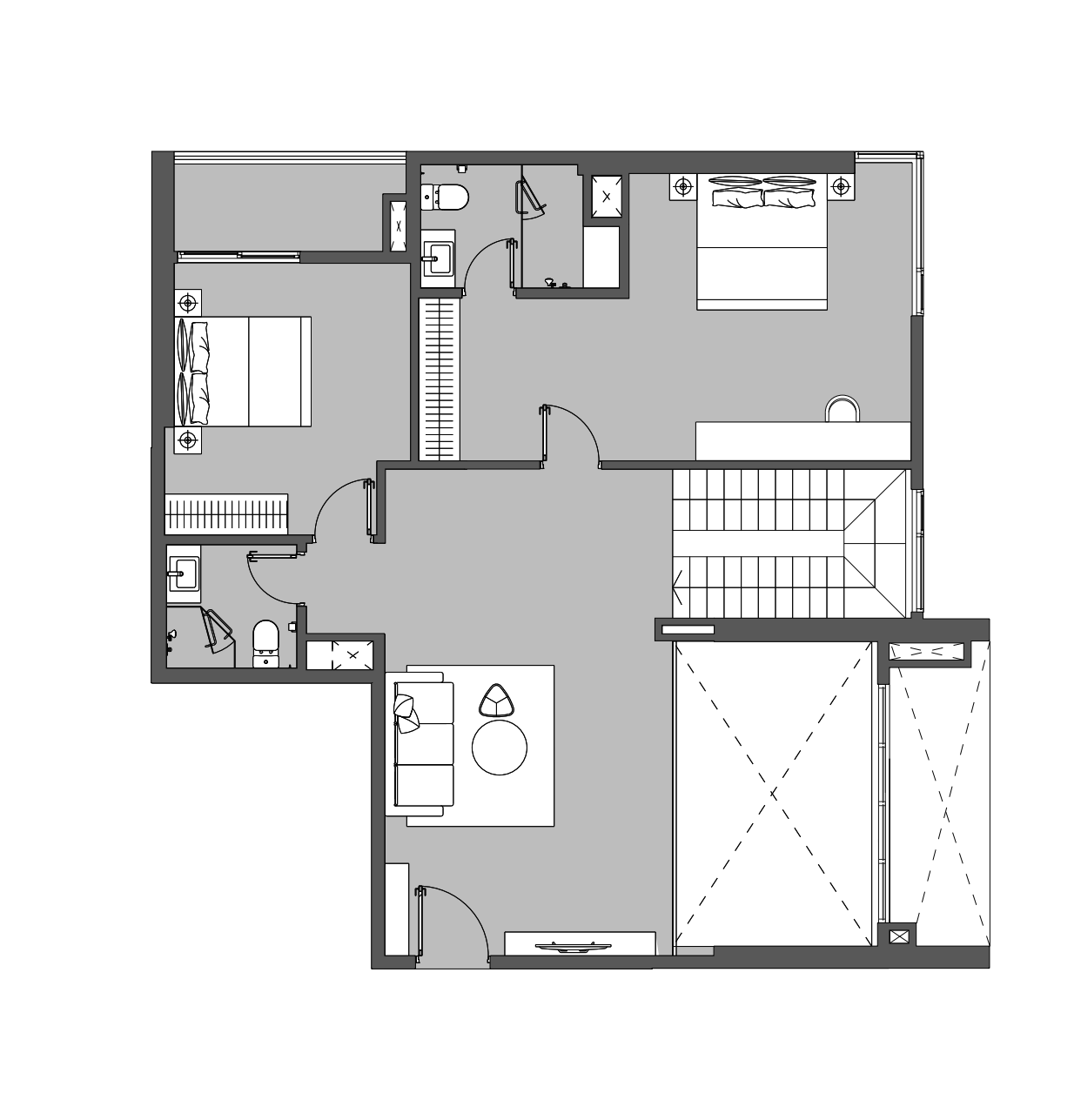
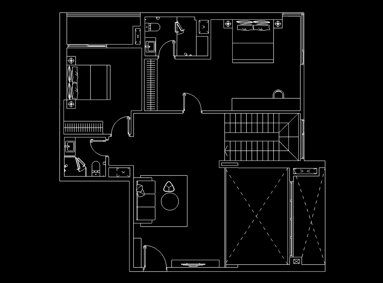
The source is a clean presentation plan rather than a dimensioned construction drawing. The result shows the extracted geometry on a dark CAD canvas.
Scale notice: this image does not provide a verified scale or known real-world dimension. The converted drawing is a starting draft. Calibrate it with a reliable measurement and obtain professional review before design, estimation or construction use.
What the conversion retained
The strongest part of this result is structural organization. Exterior and interior wall outlines remain recognizable, door swings and window openings are visible, and the stair layout is preserved. Many smaller symbols—including beds, cabinets, bathroom fixtures and seating—also remain available as linework.
Where this can save drafting time
When the only available reference is an image, manually tracing every wall, door swing, stair tread and furnishing symbol can take significant time. An initial CAD conversion can move the workflow from blank-canvas tracing to targeted cleanup.
- Rebuilding an editable base drawing from a customer-supplied plan image.
- Preparing an early layout for renovation or interior-design discussion.
- Recovering visible geometry when the original DWG or DXF is unavailable.
- Separating repetitive tracing work from the decisions that require professional judgment.
What still needs to be checked
A clean visual match does not prove that the drawing is dimensionally correct or construction-ready. Before using the file downstream, inspect the actual CAD rather than relying only on the preview.
- Scale and dimensions: calibrate the entire drawing using at least one trustworthy measurement.
- Wall geometry: check wall thicknesses, corners, junctions and parallel alignment.
- Openings: verify door widths, swing directions, windows and their exact positions.
- Line quality: remove duplicate segments, close small gaps and simplify unnecessary short lines.
- Missing information: add levels, materials, structural details, annotations and dimensions manually.
A practical floor-plan-to-CAD workflow
- Use the highest-resolution plan available and avoid screenshots with compression or perspective distortion.
- Generate the first CAD result and compare the overall footprint and room relationships with the source.
- Open the actual CAD file to inspect layers, intersections, open contours and duplicate geometry.
- Calibrate the drawing with a known wall length, room width or other verified measurement.
- Correct critical geometry and add the dimensions and technical information required for the intended use.
The conversion can reduce tracing effort, but responsibility for measurement, code compliance and construction accuracy remains with the qualified person preparing the final drawing.
Convert your own floor plan image
Upload a floor plan, sketch, photo or technical drawing, then inspect the generated DWG/DXF result.