Converting a floor plan image to CAD means interpreting pixels as editable geometry such as lines, arcs and polylines. It can remove much of the repetitive tracing work, but visual similarity does not prove that wall thicknesses, openings or scale are correct. A dependable workflow creates a starting drawing first, calibrates it with known measurements, and then checks the geometry required for its intended use.
1. Which floor plan images convert well?
Floor plan conversion works best when the source has clear, continuous, high-contrast linework. A plan exported directly from design software normally requires less cleanup than a compressed screenshot or an angled phone photo.
| Source image | Typical difficulty | Recommended preparation |
|---|---|---|
| High-resolution exported floor plan | Lower | Convert directly, then verify scale and small symbols. |
| Presentation plan with furniture, fills and text | Medium | Keep the main structure and expect cleanup around fills and detailed symbols. |
| Phone photo of a printed plan | Higher | Crop the page, correct perspective and even out lighting first. |
| Small or repeatedly compressed JPG | Higher | Find the original if possible; otherwise expect more gaps and fragmented lines. |
Before conversion, zoom to 200% and inspect several wall corners, a door or window symbol, and any dimension text. If the important linework already breaks into blurred pixels or compression blocks, the generated CAD is likely to contain fragmented geometry as well.
2. How to convert a floor plan image to CAD
Step 1: Start with the best available source
Use the original PNG, high-quality JPG or exported PDF page whenever possible. Avoid downloading an image after it has passed through a messaging app, because additional compression can erase thin wall lines and damage small text. When photographing paper, keep the camera parallel to the page and avoid shadows, glare and curled edges.
Step 2: Crop and correct perspective
If the photographed page appears trapezoidal, correct its four corners before conversion. Perspective distortion turns parallel walls into converging lines, and converting the image without correction simply preserves the wrong angles as CAD geometry. Cropping out the desk, page border and background shadows also reduces unwanted lines.
Step 3: Upload the image and choose DWG or DXF
Upload the prepared floor plan to the image-to-CAD tool and choose an output that fits the next application. DWG is commonly used for continued work in AutoCAD-compatible environments. DXF has broad support for exchanging geometry among CAD, CAM and graphics applications.
Step 4: Check the overall layout before details
First compare the building footprint, room relationships, stairs and major openings with the source. If the overall layout is incorrect, improve or replace the source rather than spending time cleaning the wrong geometry. Once the structure looks reasonable, open the actual DWG or DXF file instead of judging only from a rendered preview.
Step 5: Calibrate, clean and organize
Set the real scale using verified measurements, then inspect the file for duplicate objects, open contours, small gaps and unnecessary short segments. Finally, organize walls, openings, furniture, text and dimensions on appropriate layers and add information missing from the image.
3. How to calibrate real-world scale
An image stores pixel distances. It does not automatically tell CAD how many millimeters, inches or feet each pixel represents. If the source has no scale bar and no trustworthy dimension, absolute size cannot be recovered from the image alone.
- Identify a verified real-world distance, such as a measured room width, wall length or opening.
- Measure the corresponding segment in the converted CAD file.
- Use the CAD application's reference scaling tool so the current length matches the real measurement.
- Check two or more additional known distances to detect stretching or perspective distortion in the source.
4. What to inspect in the generated CAD
Walls and corners
Confirm that exterior and interior walls are continuous, wall thicknesses are sensible, and right-angle corners have not become skewed. A thick raster line or gray fill edge may create extra parallel objects; decide which lines represent the intended wall faces.
Doors, windows and stairs
Verify opening positions, door widths and swing directions, window extents and stair geometry. Door arcs, narrow frames and closely spaced stair treads are common areas for broken or duplicated segments.
Duplicate lines, gaps and closed contours
Antialiasing, shadows and both edges of a thick raster line can become adjacent CAD objects. Use a duplicate-object cleanup command to remove overlaps, then join or extend segments where small gaps remain. Keep join tolerance conservative so nearby objects that should remain separate are not combined.
Layers, text and dimensions
Automatic conversion primarily recovers visible geometry; it may not reconstruct the semantic layer structure of the original design. Move walls, openings, furniture, text and dimensions to useful layers, and re-enter critical text or measurements when accuracy matters.
Information required by the final use
A floor plan image often omits material specifications, levels, construction details, structural information and tolerances. Even a visually complete conversion does not become a construction document automatically. Qualified review is required before estimating, fabrication or construction.
5. Real example: furnished floor plan to CAD
Case 112742 starts with a detailed plan containing walls, doors, windows, stairs, beds, cabinets, sanitary fixtures and seating. The generated result retains the main spatial relationships and much of the interior linework, making it useful as a starting draft for further CAD editing.
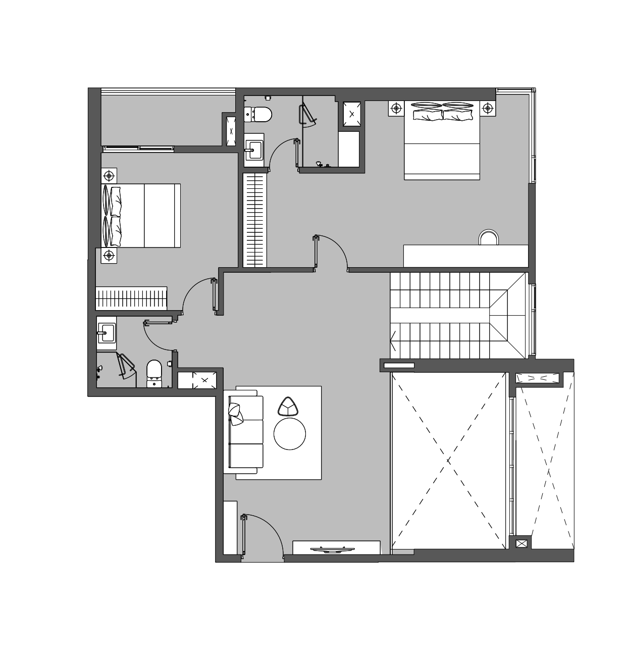
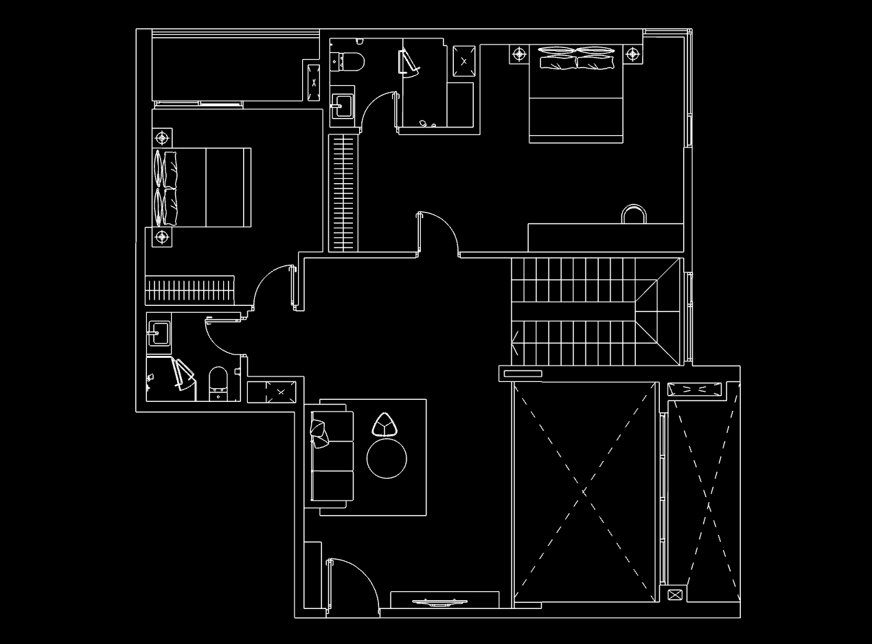
This comparison shows the visual conversion result. The source does not provide a verified scale or measured dimensions, so the output must not be used directly for construction.
Another example: a photographed hand-drawn floor plan
Working from a paper sketch? Case 115239 shows a hand-drawn floor plan photo converted into CAD, with two bedrooms, bathrooms, a living and kitchen area, and a garage.
Open the full case study to compare the original photo with the generated room layout, door swings, windows and fixtures, or explore the actual CAD drawing online.
6. Floor plan image to CAD FAQ
Can a floor plan image be converted directly to CAD?
A floor plan image can be converted into editable CAD linework, but the result normally needs scale calibration and checks for walls, openings, duplicate segments and small gaps. An image without reliable dimensions should not be treated as a construction drawing.
Will a JPG or PNG floor plan produce real dimensions in CAD?
Only if the source includes trustworthy dimensions or the generated drawing is calibrated against at least one verified real-world measurement. Pixel dimensions alone do not establish millimeters, inches or feet.
Should I convert a floor plan image to DWG or DXF?
DWG is a common choice for continued editing in AutoCAD-compatible workflows. DXF is widely supported for exchanging geometry between CAD, CAM and graphics applications. Choose the format supported by the software used next.
Why does converted CAD contain duplicate lines or gaps?
Low resolution, JPEG compression, shadows, antialiasing, gray fills, text and detailed furniture symbols can become extra or fragmented geometry. Better source quality and careful CAD cleanup reduce these problems.
Test one of your own floor plans
Generate a DWG or DXF, inspect the actual geometry, and determine how much cleanup your workflow requires.